![[DoCAN] Vehicle Diagnostic Communication Part 8 [ISO-TP 4]](https://www.simulationroom999.com/blog/wp-content/uploads/2022/11/01_eyecatch-4.png)
Click here for back issues.
https://www.simulationroom999.com/blog/diagnostic-communication-en-back-issue/
Introduction.
Continuation of the description of the network layer of vehicle diagnostic communication.
This time, an overview of the types of frames used to construct the messages.
Image of communication
I think it’s OK to explain where the addressing format is to be sent in the previous section.
However, the frame composition when actually sending is still unknown.
Since the data field of one frame of CAN is limited to 8 bytes, does that mean a maximum of 8 bytes?
The answer is no.
Up to 4095 bytes can be sent.
N_PCI (Network Protocol Control Information) allows more than 8[bytes] of data to be sent and received at the start of each CAN frame.
This is similar to the image of IP fragmentation in Ethernet.
And DoCAN is simpler.
IP fragmentation is an Internet Protocol (IP) process that breaks packets into smaller pieces (fragments), so that the resulting pieces can pass through a link with a smaller maximum transmission unit (MTU) than the original packet size. The fragments are reassembled by the receiving host.
Wikipedia(https://en.wikipedia.org/wiki/IP_fragmentation)
Types of frames
For ease of explanation, the addressing format is assumed to be normal fixed addressing.
(If the size of CAN’s DataField changes depending on the addressing format, it will be difficult to explain…)
Types of frames are listed below.
- SF(Single Frame)
- FF(First Frame)
- FC(Flow Control)
- CF(Consecutive Frame)
Basic Flow
The contents of each frame are explained later, but the basic flow is explained below.
First, for transmissions of 7 bytes or less, it is SF.
Since only one CAN frame is needed, even if a figure is drawn, it will be as simple as this.

And it is the transmission of more than 8 bytes that increases the difficulty of vehicle diagnostic communication.
The figure below illustrates this.
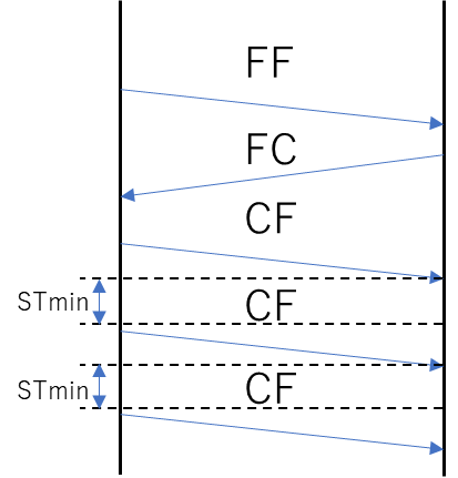
The sender does not send unilaterally, but waits for the FC response from the receiver once.
The FC informs the sender of the CF transmission interval and the timing of another FC request.
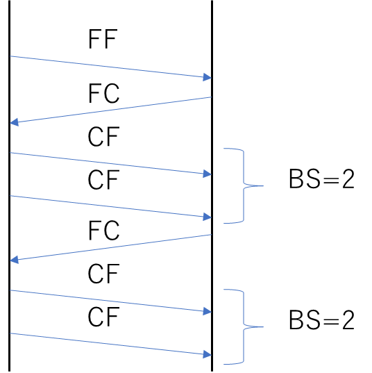
The parameters that appear in the FC are as follows.
- STmin (SeparationTime minimum): Interval between CFs
- BS(Block Size): Number of CFs until the next FC response
The figure below shows the parameters.
STmin and BS are parameters that assume low ECU performance.
Many vehicle networks have specifications that are concerned with performance, and the same will be true for vehicle diagnostic communication.
There are many things to be concerned about, but if you understand them one by one, you will be relatively okay.
Conclusion.
- CAN multiple frames can send/receive up to 4095 bytes.
- The parameter N_PCI is at the start of each frame, and there is a mechanism to concatenate the frames well.
- There are two main transmission methods depending on the number of data to be sent.
- If the number of data to be sent is 7 bytes or less, single frame transmission is used.
- If the number of transmitted data is 8 bytes or more, it is a multi-frame transmission.
- Multi-frame transmission has a mechanism to control the throughput by setting the CF transmission interval and the timing for receiving another FC with FC.
Click here for back issues.
コメント