![[CanTp] Vehicle Diagnostic Communication Part 19 [Simulation 7]](https://www.simulationroom999.com/blog/wp-content/uploads/2022/11/01_eyecatch-15.png)
Click here for back issues.
https://www.simulationroom999.com/blog/diagnostic-communication-en-back-issue/
Introduction.
Let’s simulate ISO-TP. series.
This time, we will talk about programming using pyton-can.
Towards CAN control with python-can
Last time, I ran the python-can modules can.player and can.logger, but I don’t feel like I controlled them, just that I got confirmation of their operation.
Currently, the only thing I can say is “I ran the included sample programs without knowing what’s in them.”
So this time, I want to write some Python code to get a feel for how it’s being controlled!
CAN interface devices that python-can can work with
Before writing Python code, let us list below the CAN interface devices that are supported by python-can.
- SocketCAN
- Kvaser’s CANLIB
- CAN over Serial
- CAN over Serial / SLCAN
- IXXAT Virtual CAN Interface
- PCAN Basic API
- USB2CAN Interface
- NI-CAN
- isCAN
- NEOVI Interface
- Vector
- CANalyst-II
- SYSTEC interface
python-can supports a variety of devices.
It also supports Vector devices, so as a result, it can support the Virtual CAN Bus.
It seems to be very versatile, as it can work with other devices as well.
python-can send and receive
The following image will be used for this experiment.
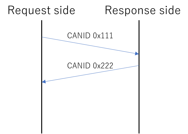
As you can see, it sends CANID 0x111, and when it receives it, it immediately replies with CANID 0x222.
It is simple, but there is a sense of control.
To get this configuration, we need to create two programs, one for the request side and one for the response side.
python-can request-side code
The code for the request side is as follows.
import can

# Bus connection
bus = can.interface.Bus(bustype='vector', channel='0', bitrate=500000)

# sent data(CANID 0x111、DLC:8、Data:01 02 03 04 05 06 07 08)
send_msg = can.Message(
	arbitration_id=0x111,
	extended_id=1,
	data=[0x01, 0x02, 0x03, 0x04, 0x05, 0x06, 0x07, 0x08])
print('Send msg : %s' % send_msg)

# transmission
bus.send( send_msg )

# reception
recv_msg = bus.recv(timeout=1)
print('Recv msg : %s' % recv_msg)
Connect to Virtual CAN Bus with bus connection, create CAN frame with Message, send with send, receive with recv.
python-can response side code
The code for the response side is as follows.
import can

# Bus connection
bus = can.interface.Bus(bustype='vector', channel='0', bitrate=500000)

# reception
while True:
	recv_msg = bus.recv(timeout=1)
	if recv_msg != None:
		print('Recv msg : %s' % recv_msg)
		break

# sent data(CANID 0x222、DLC:6、Data:0A 0B 0C 0D 0E 0F)
send_msg = can.Message(
	arbitration_id=0x222,
	data=[0x0A, 0x0B, 0x0C, 0x0D, 0x0E, 0x0F])
print('Send msg : %s' % send_msg)

# transmission
bus.send( send_msg )
It will wait for reception in a loop, and when received, it will create a CAN frame for transmission and send it.
python-can request-response results
The results of each execution are as follows.
Request side
Send msg : Timestamp:        0.000000   ID: 00000111 X DLC:8 01 02 03 04 05 06 07 08
Recv msg : Timestamp: 1596259123.521760 ID: 00000222 X DLC:6 0a 0b 0c 0d 0e 0f       Channel: 0
Response side
Recv msg : Timestamp: 1596259123.514021 ID: 00000111 X DLC:8 01 02 03 04 05 06 07 08 Channel: 0
Send msg : Timestamp:        0.000000   ID: 00000222 X DLC:6 0a 0b 0c 0d 0e 0f
The following are the results recorded by can.logger at the same time.
Begin Triggerblock
 0.000000 Start of measurement
 0.000000 1  111x            Rx   d 8 01 02 03 04 05 06 07 08
 0.001450 1  222x            Rx   d 6 0A 0B 0C 0D 0E 0F
End TriggerBlock
I feel like I have it under control perfectly.
Glad it’s working fine!!!
Conclusion
- Listed the devices supported by python-can.
- Sending/receiving by python-can was realized.
Click here for back issues.
コメント