![[Dcm] Vehicle Diagnostic Communication Part 64 [Simulation 3]](https://www.simulationroom999.com/blog/wp-content/uploads/2023/01/01_eyecatch_.png)
Click here for back issues.
https://www.simulationroom999.com/blog/diagnostic-communication-en-back-issue/
Introduction.
Explanation of the AUTOSAR-Dcm interface.
This article will explain the configuration in a graphical representation, which will then be further broken down into sub-modules.
Figuring out the AUTOSAR-Dcm interface specification
First of all, the following figure shows the AUTOSAR-Dcm configuration, which is the result of the previous assignment.
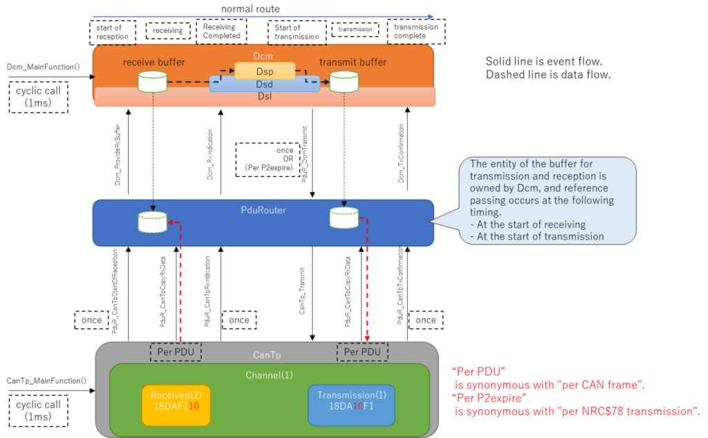
One new thing that has appeared is a PduRouter in the middle.
This is originally a function that is automatically generated by the configurator, but this article requires us to do our best to implement the matching.
The PduRouter is used to make the interfaces of Dcm and CanTp match up.
Buffer for AUTOSAR-Dcm communication
There are two more points of concern: receive buffer and transmit buffer.
Both of these buffers are managed by the Dcm.
In a typical protocol stack, each layer would have its own buffer.
If memory resources are enough and the overhead of copy processing is ignorable, such an implementation would be better.
In other words, if memory resources and copy processing are to be minimized, as in the case of ECUs, it is better to use common buffers.
This is called a “memory-saving, copy-saving design and implementation policy.”
The AUTOSAR specification has such a policy.
Internal structure of AUTOSAR-Dcm
If observed closely, the inside of AUTOSAR-Dcm is also divided into sections.
- dsl:Diagnostic Session Layer
- dsd:Diagnostic Service Dispatcher
- dsp:Diagnostic Service Processing
The roles of each are as follows.
| Module | Formal name | Description |
|---|---|---|
| dsl | Diagnostic Session Layer | Timing handling and special response behavior. |
| dsd | Diagnostic Service Dispatcher | Assignment of processing to each service (including decisions based on session and security). |
| dsp | Diagnostic Service Processing | Actual processing of each service and requests to the application layer. |
Timing handling includes P2 time, P2* time, and S3 time.
The dsd assigns the timing to each service.
However, in reality, each session may support different services, or may be locked for security reasons.
Therefore, these are also determined here.
And dsp is the actual processing for each service.
This process itself often involves accessing information held by other functions, so it plays the role of coordinating them well.
The configuration that determines these behaviors is the hard part, though.
Conclusion
- The interface specification of AUTOSAR-Dcm is figured out.
- The buffers for communication are managed by AUTOSAR-Dcm, which is a memory-saving and copy-saving design implementation.
- AUTOSAR-Dcm consists of three sub-modules.
- dsl: Diagnostic Session Layer.
- dsd: Diagnostic Service Dispatcher.
- dsp: Diagnostic Service Processing.
Click here for back issues.
Embedded Networking With CAN and CANopen
Bosch Automotive Handbook
Diagnostic Communication with Road-Vehicles and Non-Road Mobile Machinery (English Edition)

Road Vehicles – Diagnostic Communication
AUTOSAR A Complete Guide – 2021 Edition (English Edition)

Autosar Compendium: Application & RTE: Based on AR4.0.3
AUTOSAR Complete Self-Assessment Guide
コメント