![[DoCAN] Vehicle Diagnostic Communication Part 3 [CAN 2]](https://www.simulationroom999.com/blog/wp-content/uploads/2022/10/01_eyecatch-25.png)
Click here for back issues.
https://www.simulationroom999.com/blog/diagnostic-communication-en-back-issue/

Introduction.
This article is the first part of a series on the data link layer of CAN, ISO 11898-1.
After all, why not just do a Google search?
After all, the datalink layer can be informed there by a Google search.
Wikipedia

If you are confident in your Japanese, it is best to read ” Beginning CAN/CAN FD” from Vector’s documentation.

I will try to supplement the information that may not be included in Vector’s document, since it is too blunt to say so.
CAN protocol trials
In the last issue, the baud rate to be used was set to 500 kbps.
Do you know how this can be determined?
You may think it is the same as UART or something like that.
In the case of UART, the baud rate clock would be created by dividing the system clock or peripheral clock.
In the case of CAN, however, the contents are a bit more complicated.
This is the first ordeal for those beginning to investigate CAN.
This is commonly referred to as “the problem of not knowing how to set the CAN baud rate”.
If you are using Vector’s tool CANoe, etc., you will not have to worry about this.
This is only because CANoe hides the detailed settings well.
In fact, you can set the fine settings, so if you do that, you may get a glimpse of the magic world this time.
CAN baud rate
The peripheral clock mentioned earlier for the UART is the system clock for the CAN controller.
Up to this point, there is no difference between UART and CAN.
In the case of UART, the baud rate is determined by dividing the system clock.
In the case of CAN, however, a clock that is finer than the baud rate is specified.
This is called a quantum.
Multiple quantums determine one bit of time.
The question that may be raised here is, “How many quantums are enough for one bit of time?” This has not been determined.
It may be 1 bit for 12 quantums or 1 bit for 16 quantums.
This is calculated backward from the baud rate you want to set.
It would be simpler as a specification fixed at “1 bit at 16 quantums” from the beginning.
In fact, UART, for example, internally determines 1 bit with a fixed number of quantums.
Because the baud rate is fixed, the baud rate setting side does not need to worry about it.
On the other hand, CAN is designed to be aware of the quantum.
Why is this?
The reason is to set the sampling point.
CAN Sampling Points
You might think that sampling point is a new term, but it is not a CAN-specific term.
The concept of sampling point is inherent in UART as well, just not visible from the software side.
In the case of UART, the sampling point is fixed at 50% in most cases.
In some cases, only the start bit may be at the 75% position.
You may be wondering what “50%” or “75%” means.
Just picture the UART waveform.
At what point in the waveform should we sample to get a stable High and Low signal?
The answer is the timing in the middle farthest from the High and Low change points.
When we say 50%, we are referring to this middle timing.
In the case of CAN, this sampling point can be changed arbitrarily.
In fact, it is not completely arbitrary, but there is a range of settings.
The standard range is 50% to 90%.
Baud rate and sampling point
Perhaps you have not yet arranged the information in your mind.
Therefore, the case of 75% sample point is indicated in the figure below.
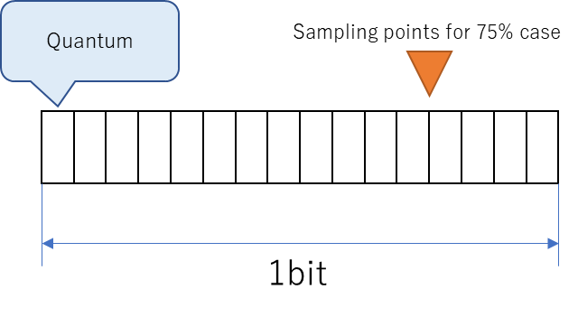
While looking at this figure, try to envision the following steps:
- set the sampling point to 75[%].
- set the number of quantums to 16.
- if you want 500[kbps], use 500[kbps]×16[qt]=8000[kHz]=8[MHz] as the CAN system clock.
- if you want to set the sampling point to 75[%], set it to sample around 12[qt].
What do you think?
Are you starting to see the flow of how to set the CAN baud rate?
As you can see, setting the baud rate of CAN is a bit time-consuming.
Conclusion.
- Basically, a Google search can provide information on the CAN data link layer.
- CAN baud rate setting is special.
- It is not possible to set the baud rate directly, but the quantum time, which is a decomposition of 1 bit, is determined first.
- Since the total quantum is the baud rate, it is necessary to calculate backward from the baud rate you want to set.
- CAN can adjust the sampling point.
- It can be decided at which quantum in the total quantum to sample.
- This is often expressed as [%].
- 50[%] for the middle, 75[%] for slightly behind (around 3/4).
Click here for back issues.


コメント