![[DoCAN] Vehicle Diagnostic Communication Part 4 [CAN 3]](https://www.simulationroom999.com/blog/wp-content/uploads/2022/11/01_eyecatch.png)
Click here for back issues.
https://www.simulationroom999.com/blog/diagnostic-communication-en-back-issue/
Introduction.
This article is the second part of a series on the data link layer of CAN, ISO 11898-1.
Review CAN baud rate settings
This is a continuation of the explanation of the data link layer of CAN.
In the last issue, I discussed quantum and sampling point as it relates to baud rate.
To summarize, the system clock of CAN determines the quantum time, not the baud rate as it is.
As for the baud rate, it is OK to be aware of the quantum time, but as for determining the sampling point, you need to know about the segment.
(“You’re going on about terms you don’t know any better?!” I’m sure many of you are thinking…)
About segments in CAN
A segment consists of one or more quantums.
And they are divided into four types.
- Synchronization Segment
- Propagation Segment
- Phase Segment1
- Phase Segment2
All of these segments total one bit.
The table below summarizes what each of these segments means.
| Segment | Function |
|---|---|
| Synchronization Segment | Bus-level edges occur |
| Propagation Segment | Compensates for delay time |
| Phase Segment1 | Before sampling point |
| Phase Segment2 | After sampling point |
Even here, many people may still not understand it well.
Therefore, I will try to describe it as a figure.
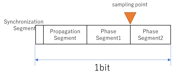
What I am trying to say here is that once the number of quantums for each segment is determined, the sampling point is also determined.
And if you look closely, it appears that Synchronization Segment and Propagation Segment can be combined into one segment when considered in terms of sampling points.
Certainly, it is not necessary to determine the sampling point.
However, it is a necessary concept for the CAN hardware specification.
The Synchronization Segment is where the edges are made, so it is obviously necessary.
The Propagation Segment is for line delay compensation and is stretched and contracted in a way that is not seen by the software.
In fact, some CAN controllers set the Propagation Segment and Phase Segment 1 in an integrated state, so you don’t have to worry about it too much.
Incidentally, the expression when Propagation Segment and Phase Segment1 are integrated is roughly as follows.
- Propagation Segment+Phase Segment1:tseg1
- Phase Segment2:tseg2
In other words, it can be said that different CAN controllers have different expressions.
Therefore, it is better to remember both terms.
The above are the minimum CAN specifications that should be known for vehicle diagnostic communication.
Conclusion.
- To determine the sampling points, the number of quantums in each segment must be determined.
- There are 4 types of segments, each for 1 bit.
- Synchronization Segment.
- Propagation Segment.
- Phase Segment1.
- Phase Segment2.
- Propagation Segment + Phase Segment1 is called tseg1, and Phase Segment2 is called tseg2.
Click here for back issues.
コメント